Climate modeling by the International Energy Agency recommends Carbon Capture and Storage (CCS) as the crucial component to stabilizing global climate. The US Department of Energy recently predicted ten-fold growth of the CCS industry by 2030 suggesting sequestration of 350-1000 GT by the middle of this century. CCS in the United States has been further incentivized by climate-related provisions in the Inflation Reduction act. With all of this activity surrounding carbon capture and storage, it’s a good time to explore how and where CCS can be implemented efficiently.
CCS is a proven and safe technology that prevents carbon dioxide (CO2) from being released from point sources into the atmosphere or removes it directly from the atmosphere. The technology involves capturing (purifying) CO2 produced by industrial plants, such as steel mills, chemicals and cement plants, coal and natural gas-fired power plants, and oil refineries, compressing it for transportation and then injecting it deep underground – more than 2600 ft below the surface – into a carefully selected geological storage site, where it will be trapped and permanently stored in the porous rock.
Many advocates of subsurface storage point to existing infrastructure from hydrocarbon exploration and production as a great fit for CCS. Beyond utilization for enhanced oil recovery, depleted hydrocarbon reservoirs can also be used for storage once production has declined and become uneconomical. The advantages of subsurface storage into depleted hydrocarbon reservoirs are multifold: the reservoir geometry and properties are well known from decades of production from these reservoirs, the trapping mechanism is well understood, the cap rock integrity is established, and the fluid flow within the reservoir has often been history matched at production wells. However, limited storage capacity of depleted reservoirs, along with penetration by a significant number of producing or abandoned wells, constitute potential risks of leakage pathways to shallow aquifers or to the ground surface.
This has led some early adopters of CCS to investigate deep saline aquifers as storage targets. The advantages of saline aquifer storage are significantly greater available pore space compared to the depleted hydrocarbon reservoirs and a smaller number of well penetrations, reducing risks of potential leakage pathways through these wells. However, lack of significant amount of reservoir data in saline aquifers increases uncertainty in defining reservoir confinement, cap rock integrity, and fluid flow behavior in the reservoir due to the absence of history matching. Therefore, saline aquifer storage assessment requires a comprehensive reservoir characterization and modeling before large-scale CO2 injection planning. The success of CO2 storage depends on balancing the conflicting benefits and challenges of ‘brownfield’ versus ‘greenfield’ reservoirs and aquifers.
As with conventional oil and gas, subsurface data and insights are at the core of decision making to identify appropriate subsurface storage locations. Access to expansive subsurface well and seismic data and decades of oil and gas exploration experience provide TGS a unique advantage of developing integrated CCS solutions. TGS New Energy Solutions has developed a prospecting/ screening tool for CCS, Carbon AXIOM, a data-driven solution of estimated volumetrics for storage potential of injected CO2 in depleted oil and gas reservoirs and saline aquifers. Data available for this solution includes geological data (wireline logs, directional surveys, interpreted formation tops, etc.), well performance data (cumulative production/ injection, forecasted EUR and completions), reservoir/fluid analysis data, and seismic data. Proprietary geologic and high-resolution basin temperature models are also integrated into the solution (Figure 1). Repurposing of existing well and seismic data, combined with available surface access and infrastructure information, could provide valuable insights for generating CCS solutions and support carbon storage initiatives across the globe.
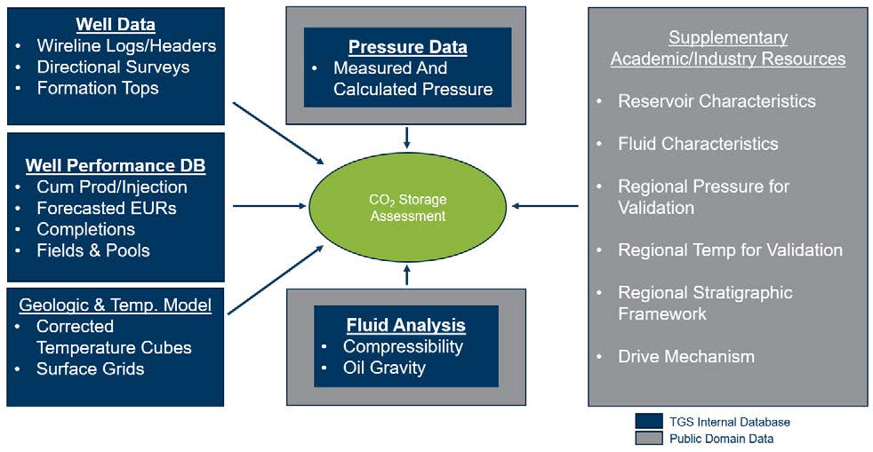 Figure 1. Data Inventory for subsurface analysis
The first set of challenges in building a CCS model is standardization of the reservoir intervals and access to sufficient reservoir/fluid attributes to perform consistent storage capacity calculations across a large area. Thankfully, TGS data provides a clean, standardized, commercial dataset for interpretation. Using this data, the team developed a specialized database for depleted hydrocarbon reservoirs involving the analysis of cumulative production, forecasted production, and completion records in more than 150,000 producing wells within the area of interest within the Eagle Ford trend. The key to this analysis was tying historical production directly to the producing formations, a task that was made significantly easier by having access to TGS Well Performance Data and Stratigraphic Models. Enhanced production allocation at various formation levels was quality-controlled using desktop geoscience interpretation software through visualizing the well perforations with relevant well logs and gridded stratigraphic surfaces.
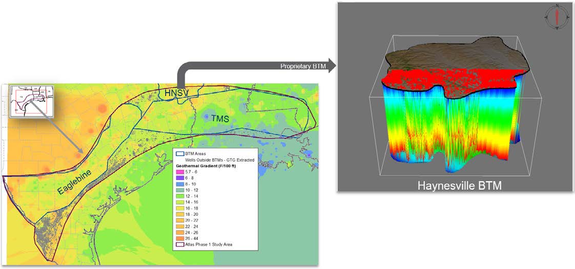 Figure 2. Temperature assignment from proprietary Haynesville Basin Temperature Model
The next step was to gather reservoir pressure (P) and temperature (T) data, which was necessary to calculate CO2 density and effective CO2 storage capacity. The solution integrates three TGS proprietary high resolution Basin Temperature Models (BTMs), the Eaglebine, the TMS (Tuscaloosa Marine Shale) and the HNSV (Haynesville) within the defined area of interest, as shown by the left-hand image of Figure 2. Temperature data were extracted along the wellbores from these temperature models to assign temperatures at the producing intervals. The right-hand image of Figure 2 shows an example of the extracted temperature along the wellbores within the Haynesville BTM area.
Pressure assignment at the producing intervals along the wellbores are equally important and can be derived from TGS Drill Stem Test data. Our internal pressure database was also supplemented with pressure data from academic resources to extract pressures at the producing intervals along the wellbores.
A material balance technique was then used to estimate the effective storage capacity for these storage units. A Monte Carlo simulation proved to be a versatile volumetric approach, as it allowed weighting of various parameters, providing P10, P50, and P90 ranges of storage outputs. Additional attributes, such as the number of well penetrations (including the inactive, shut-in, and abandoned wells) in each storage unit, were also calculated as input to further risk assessment. Finally, a web-based, interactive platform was created to analyze combining these analyses from a more than 150,000 producing well database, hydrocarbon pools were generated at 27 different formation levels, using a GIS buffering function, aggregating wells in a field producing from the same geologic formation. Figure 3 shows the distribution wells with production history (red dots) within the area of interest and the right-hand figure shows the hydrocarbon pools generated from these wells, classed and color-coded based on their estimated effective storage capacity. The term ‘storage units’ was introduced to rename individual pools, as well as a defined groupings of laterally contiguous/overlapping pools in the same stratigraphic zone where the potential of lateral migration/communication exists during the CO2 injection.
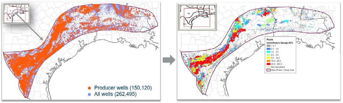 Figure 3. Hydrocarbon pools generation from distribution of producer wells within the area of interest
The resulting GIS database and support effective storage capacity screening workflows. The final dataset includes over 7,500 hydrocarbon reservoirs at 27 different formation levels, along with their reservoir and fluid attributes captured as a range, presenting values for the low, medium, and high case (Figure 4).
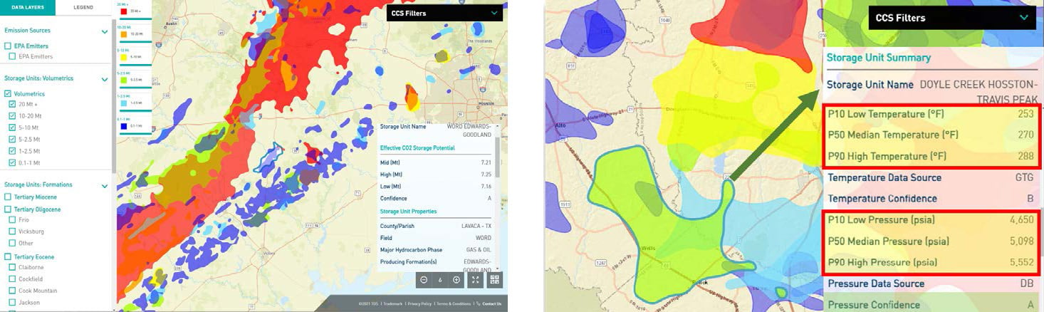 Figure 4. Depleted hydrocarbon reservoir storage units and their associated reservoir and fluid attributes in Carbon AXIOM
The solution also includes a confidence assessment attached to these storage units based on the data availability and the quality of the sources of these data. As previously discussed, saline aquifer storage has also been estimated using a similar workflow. Starting with TGS’ expansive subsurface well and seismic data library, saline aquifer intervals were mapped across a 13,000 square kilometer area of interest in shallow offshore Gulf of Mexico, as shown in Figure 5. Relevant reservoir attributes were generated through detailed petrophysical modeling of each aquifer interval. These reservoir attributes were mapped across the region and used as input for storage capacity estimation. Carbon AXIOM provides opportunity to explore the lateral and vertical variability of estimated storage capacity of the key aquifer intervals and associated reservoir parameters, and the data can be accessed at a 1x1 km2 grid level, through a user-friendly summary card in Carbon AXIOM. Figure 5 shows the mapped variability of median values of estimated Lower Miocene storage.
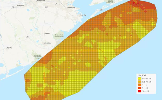 Figure 5. Lateral variability of Lower Miocene storage capacity along the area of interest.
For both depleted hydrocarbon reservoir and saline aquifers, users can utilize Carbon AXIOM as a comprehensive screening tool to identify, evaluate, and compare CO2 storage opportunities over a large geographic area and across various formation levels, and understand associated uncertainties and potential risks of subsurface storage. The web application helps to visualize/reference potential storage opportunities within the area of interest, along with other spatial layers, such as local emitters, pipelines, protected and forested lands, local power plants, and oil refineries for contextual analysis (Figure 6).
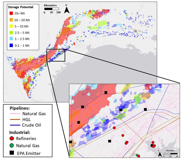 Figure 6. Database of subsurface storage analysis
combined with surface infrastructure information in Carbon AXIOM
The tool also has the capability to identify nearby depleted hydrocarbon storages for each local CO2 emission source within the 30-mile radius of the area of interest (Figure 7). Property ownership details have also been added to provide an understanding of surface ownership.
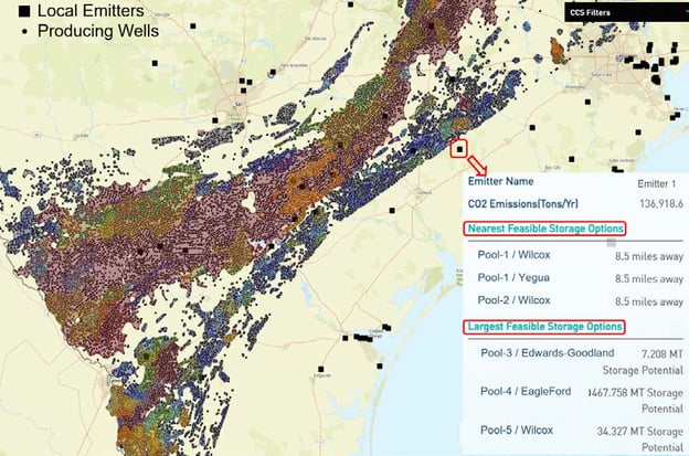 Figure 7. Identified nearby feasible storage opportunities in
Carbon AXIOM for local CO2 emission sources within the area of interest.
As individual corporations, nations, and worldwide organizations start to evaluate their climate goals, carbon capture and storage is primed to be a key driver of progress. The extension and enhancement of the tax credit through the Inflation Reduction Act of 2022 will support innovation and new deployments for a range of technologies, including CCS, that will help ensure strong commercial interest and provide a basis for potential large-scale deployment of CCS technologies. Developing a robust understanding of the available subsurface storage options in depleted hydrocarbon reservoirs or deep saline aquifers and combining that with available surface infrastructure information is critical for the success of any CCS project. TGS has combined the industry-best subsurface data library with decades of geoscience experience to create a tool that supports the practical evaluation of carbon storage opportunities with the high degree of confidence that is required for prospecting of CO2 storage locations.