

Carbon Storage Monitoring
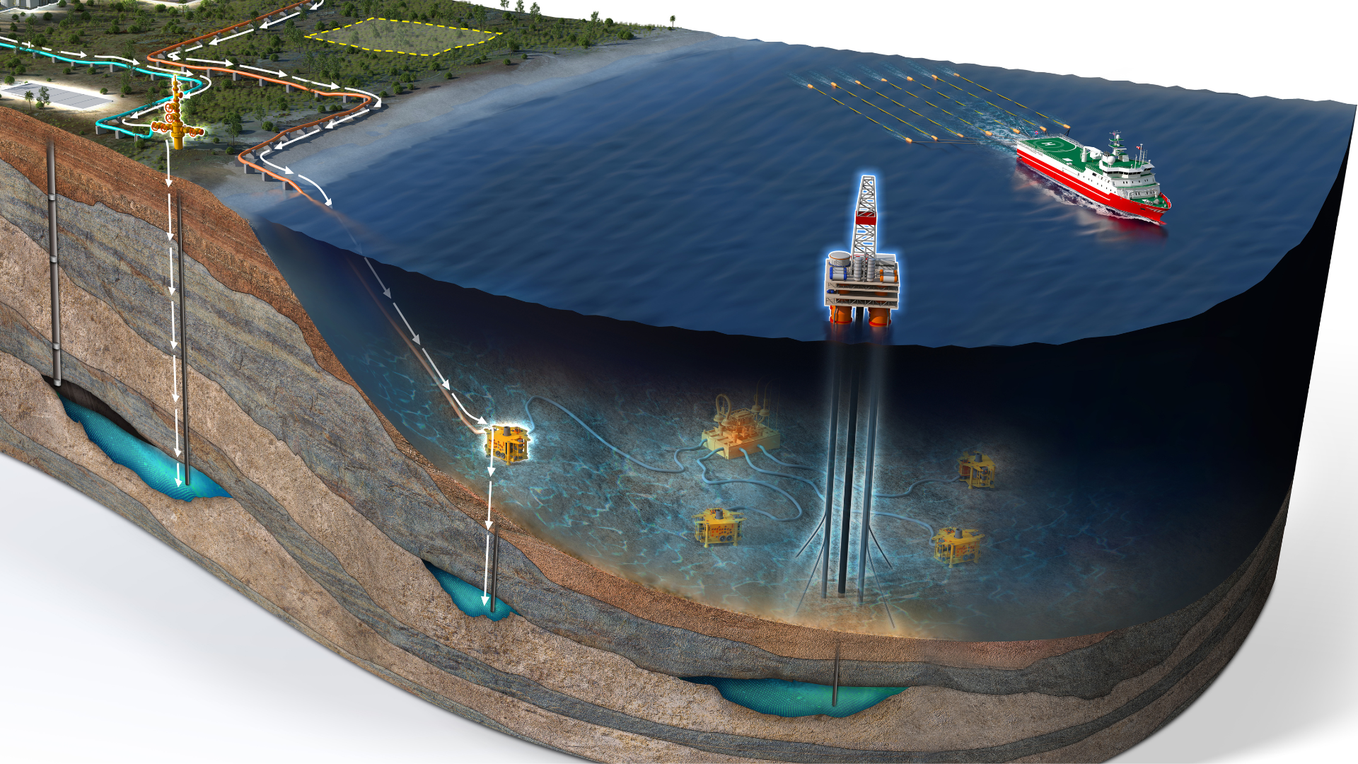
TGS combines proven advanced streamer and ocean bottom node technologies with innovative, integrated subsurface imaging solutions to monitor the full domain, from the water column to the subsurface storage reservoir. Our flexible technology portfolio enables tailored MMV solutions that balance subsurface monitoring performance with cost, operational efficiency and environmental impact throughout the life of the carbon storage project.
Carbon Storage Solutions Across the Project Lifecycle
TGS delivers integrated data, insight and monitoring solutions across the carbon storage value chain, from early prospect screening and lead maturation to site characterization and long-term surveillance. By combining industry-trusted seismic data with new baseline acquisition, early-warning capabilities and triggered or scheduled surveys, we help operators establish a robust framework for Measurement, Monitoring and Verification (MMV). This integrated approach provides the subsurface understanding needed to reduce uncertainty, manage risk and make confident decisions throughout the storage lifecycle.
The Ultimate Carbon Storage Monitoring Toolkit
Overcome the challenges of carbon storage measurement, monitoring and verification (MMV) with a comprehensive, versatile suite of tools tailored to your carbon storage needs. Our flexible 4D geophysical monitoring solutions empower customers to balance their CCS monitoring needs with geophysical and operational obstacles and costs.
- Advanced Streamer Seismic: Multi-sensor broadband seismic data acquisition, imaging, and precise characterization for cost-effective CCS planning and monitoring
- Ocean Bottom Nodes (OBN): Combine resolution with insight and repeatability with a combination of high-resolution seismic sources and ocean bottom sensors.
- Distributed Acoustic Sensing (DAS)/Vertical Seismic Profile (VSP): Vertical-in-well fiber optics will get you as close as possible to the target for on-demand repeatability.
- Ultra-High Resolution 3D (UHR3D) Seismic: Get an unrivaled image of the overburden and plume at the detail you need.
The Methodology
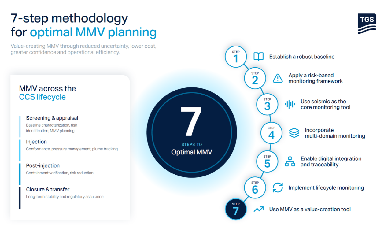
TGS’ seven-step Measurement, Monitoring and Verification (MMV) methodology begins with a robust baseline subsurface understanding of the storage site, establishing a risk-based monitoring framework aligned with project objectives. This structured approach supports accurate, cost-effective and repeatable tracking of CO₂ behavior throughout the storage lifecycle.
By detecting potential changes early, operators gain the insight needed to respond effectively, reduce uncertainty and maintain confidence in long-term storage performance.
Leveraging Fiber Optic Technology
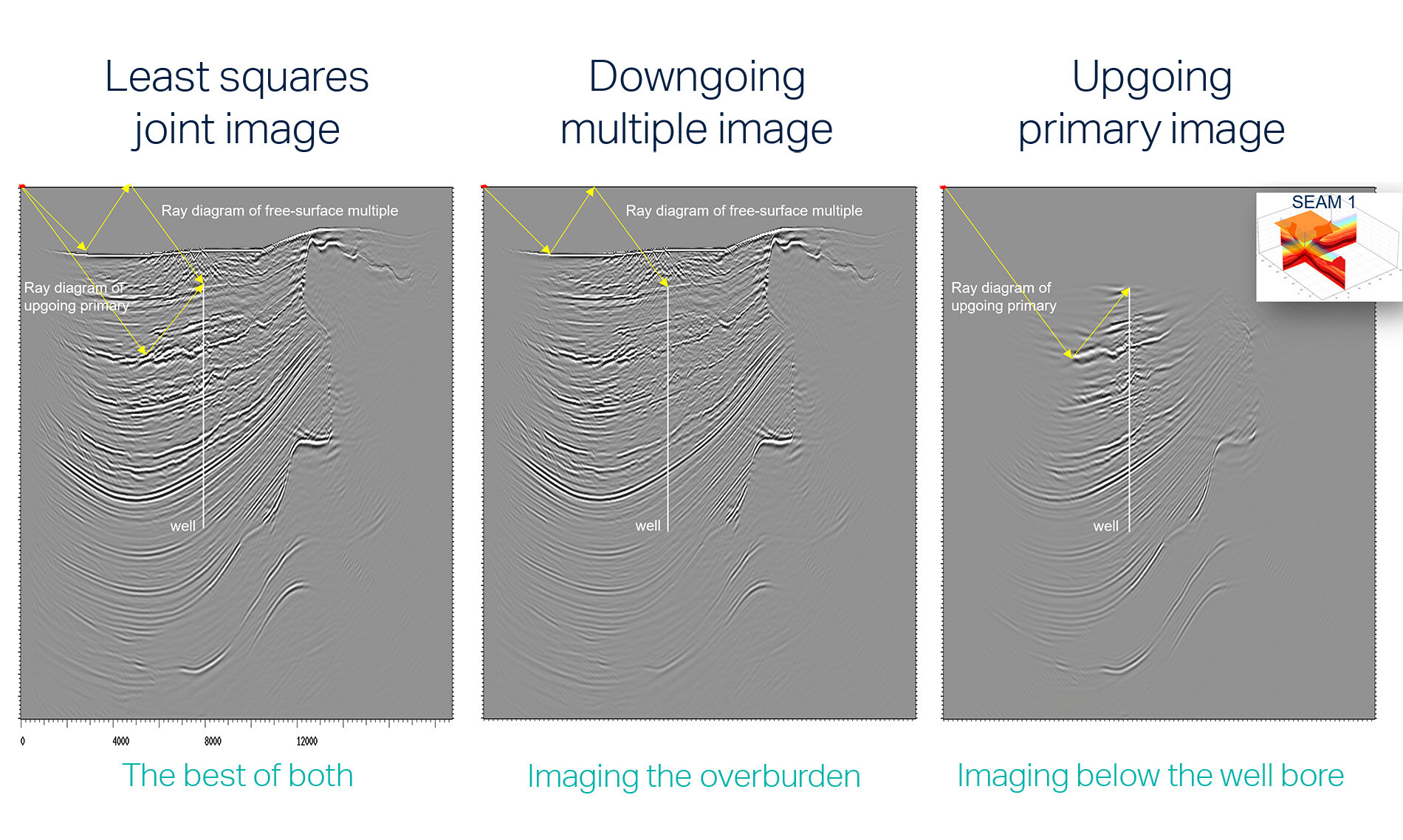
TGS seismic imaging supports cost-effective 4D CO₂ “in well” or "on seafloor” fiber optic monitoring solutions (DAS VSP). The resultant time-staggered datasets can cover the 4D needs for the injected CO₂ plume for two decades or more, reducing the cost of the overall monitoring program.
- Reduces acquisition risk and delivers a robust 4D solution
- Low cost and effective for life-of-well solution
- Technology is already widely adopted within oil and gas
Speak to a Specialist
Got a question? We're here to help. Drop us a line and provide your contact details so one of our energy data experts can get in touch with you.